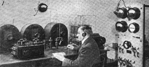
Operator at the Binghamton station

The transmitter output consisted of a 2 kW 500 cycle signal operating from a "quenching transmitter" at a frequency of approximately 190 kHz. The aerial, consisting of 4 wires, was stretched between the 97 foot 4 inch (29.7 m) open-grid framed carbon steel towers. Power for the sending unit was taken at 60 cycles, 3 phase from the station driving a Crocker-Wheeler motor generator providing 2 kW, single phase, 500 cycle current. Passing through the sending key circuit to a step-up transformer, the 500 cycle current charged a bank of six .002 µF leyden jars in parallel. These jars discharged at each half cycle across a multiple-plate quenching spark gap and through the primary of the oscillation transformer. The secondary was serially connected in the antenna-to-ground circuit. This oscillation transformer was made of two flat spiral strip copper coaxial windings having a variable self-inductance in each winding and variable coupling between windings. A wave length of about 1,600 meters (187.4 kilocycles) was generally used with approximately a 2 amps of radio frequency current set up in the antenna circuit.
The power boards located on the train were similar to the power boards installed at the train stations, but rated at half the power. It was necessary to have an aerial 150 feet long, so four regular cars of the "Lackawanna Limited" had aerial wires strung on insulators, on posts about 8 inches high, around the roofs of each car. The radiotelegraph equipment installed on board the train was located in the baggage car, and comprised of a 1 kW 500 cycle transmitter directly run from a storage battery used on the line of the axle-driven car lighting system.